QAM modulation enables fast and reliable communication in today’s digital age. QAM drives TV cables, optical networks, Wi-Fi, 4G, and 5G. In this post, we break down QAM, explain how it works in wireless systems, and show how power constraints shape its design.
“QAM is the most adopted Modulation Scheme in Modern Wireless Communication Systems“.
Watch the full video lecture below to see these concepts in action!
What is Constellation Diagram?
We need to understand constellation diagram before diving into more details. Constellation diagram is a representation of a wave, i.e., a wave can be represented as a point in the constellation diagram.
Imagine a wave ![]() with a fixed frequency “f.” We can represent this wave as a point
with a fixed frequency “f.” We can represent this wave as a point ![]() on a constellation diagram —a vector with a length and an angle, as illustrated below:
on a constellation diagram —a vector with a length and an angle, as illustrated below:
- Length =

- Angle =

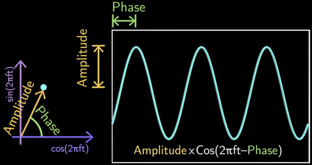
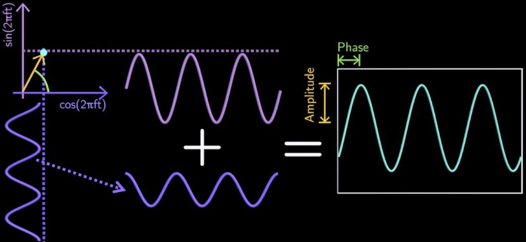
Converting a point in the constellation diagram back to the original wave is easy (as illustrated in the figure that follows):
- Project the point to vertical axis, which provides sine component
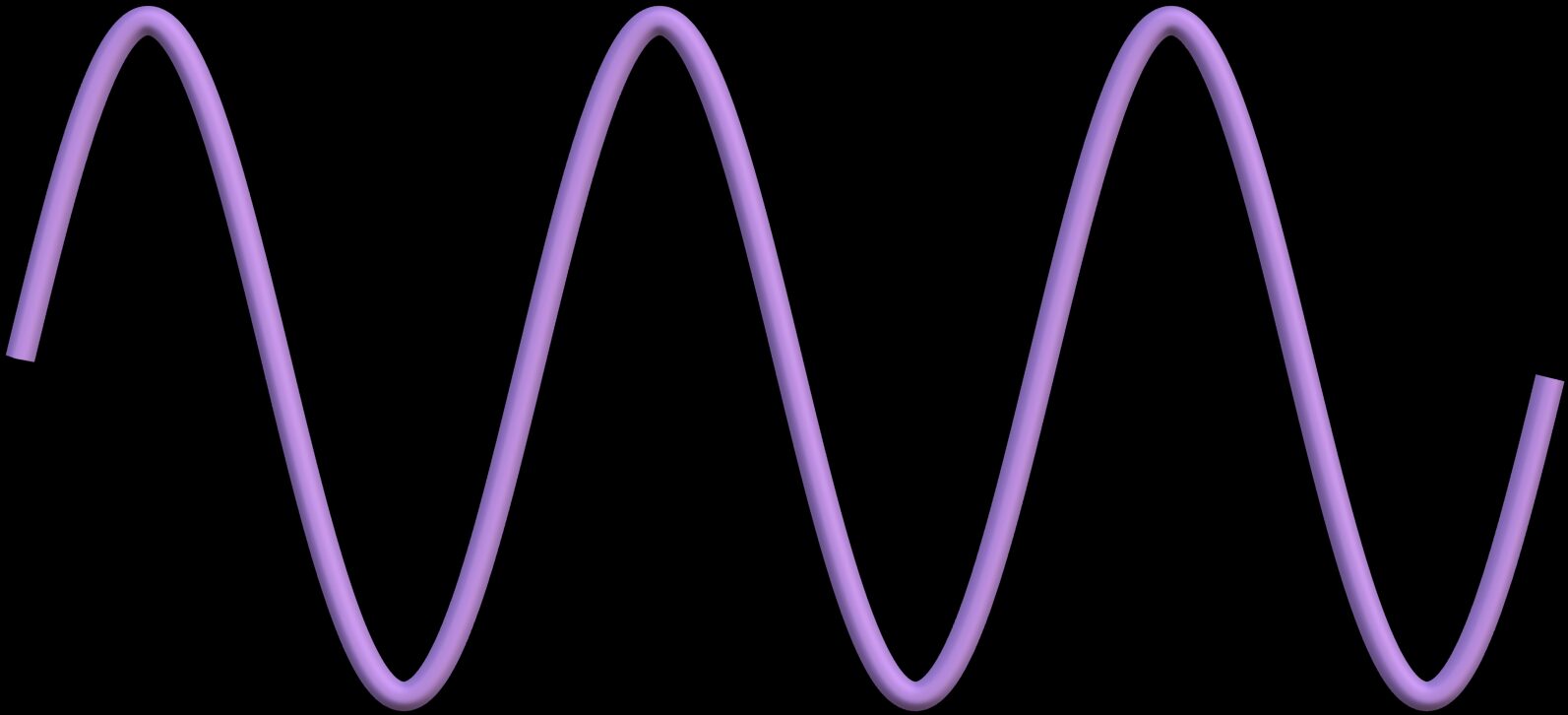
- Project the point to horizontal axis, which provides cos component

- Add these two components, you get the original wave
What is QAM Modulation?
QAM encodes data simultaneously into both the amplitude and phase of a carrier wave. That is, the transmitter encodes information by altering the carrier wave’s amplitude and phase.
For example:
- Bit 0 maps to one constellation point
 .
. - Bit 1 maps to another point
 .
.
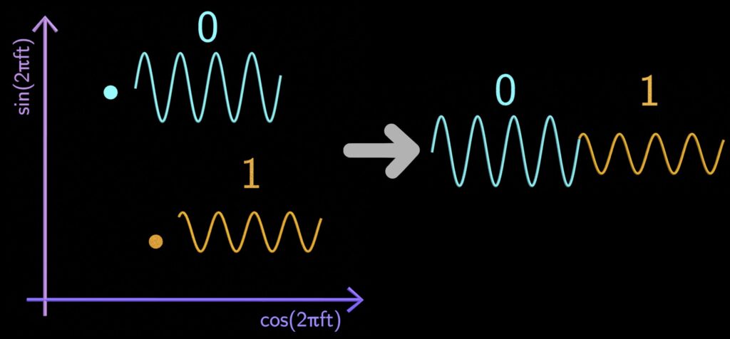
For example, to send bits “01”, the transmitter sends these points as waves with the corresponding amplitude and phase, as illustrated above.
The Decoding Process
At the receiver, the process is reversed, i.e., the receiver maps the received signal ![]() back to their constellation points (
back to their constellation points (![]()
![]() ):
):
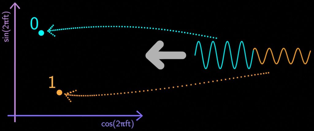
which is done as follows (illustrated in the figure that follows):
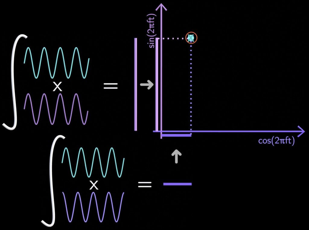
- Receiver first picks the signal received within the first symbol duration
 .
. - Receiver then multiplies the received signal
 by a sine wave
  and integrates it to get the vertical component
  of the constellation point.
 - It then multiplies the received signal
 by a cosine wave
  and integrates to get the horizontal component
  .
. - Finally, it maps these components back to the transmitted point
 in the constellation diagram. The received point
  corresponds to bit 0, hence receiver decode the signal as bit 0.
Real-World Imperfections Deviates
Received Wave
Received signals suffer from path loss, interference, and noise. These issues may shift the received constellation points farther from their intended positions.
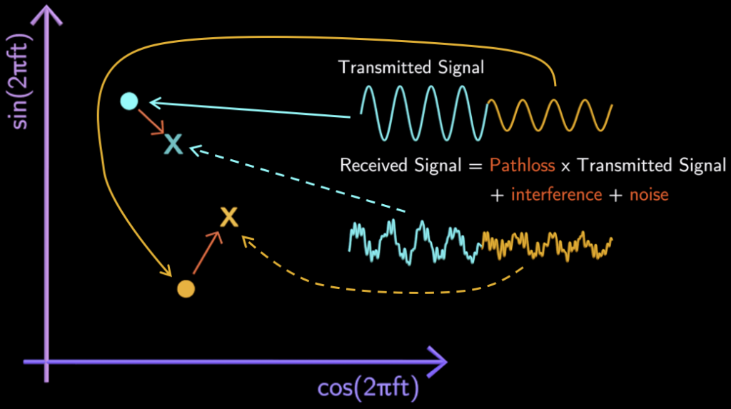
To counter this, the receiver divides the entire constellation diagram into two decision regions.
For example:
- If a received point falls in the bit 0 region, it decodes as 0.
- Otherwise, it decodes as 1.

To minimise errors, the transmitter should space the constellation points as far as possible. However, there is a catch, as explained next.
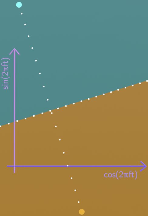
Catch: Amplitude of Transmitted Signal is Limited by Transmit Power
The length of the constellation point determines the transmit power.
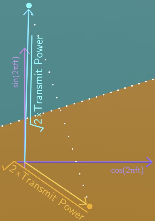
Therefore, all the constellation points must lie within a circle with radius corresponding to the maximum transmit power (maximum amplitude) allowed. This constraint forces designers to maximise the spacing between points within the circle (as illustrated below), which reduces errors during decoding.
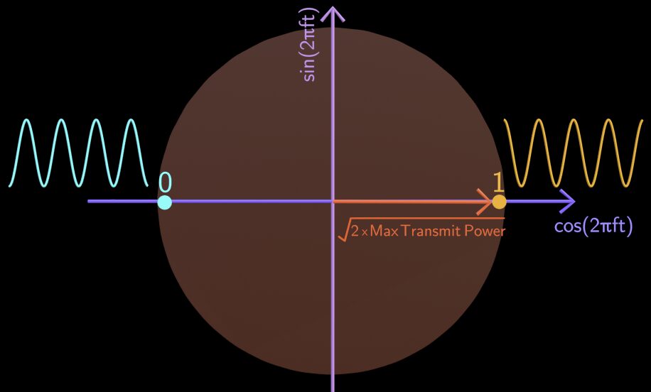
Boosting Spectral Efficiency
When interference and noise levels are low, the transmitter can encode more bits per symbol, as follows:
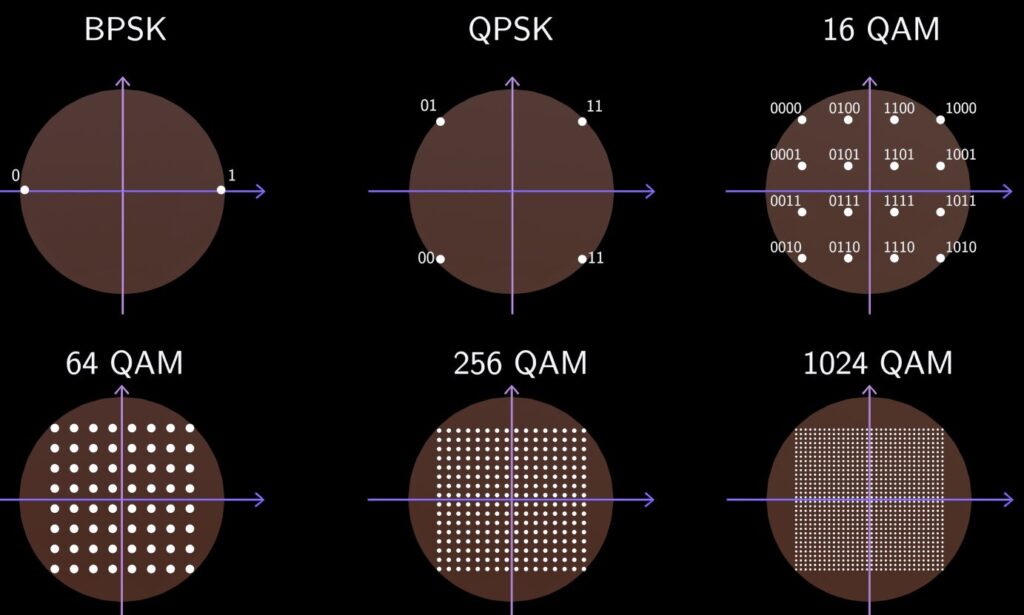
- 1 bit per Symbol: Use 2 constellation points (BPSK).
- 2 Bits per Symbol: Use 4 constellation points (QPSK).
- 4 Bits per Symbol: Use 16 constellation points (16 QAM).
- 6 Bits per Symbol: Use 64 constellation points (64 QAM).
- 8 Bits per Symbol: Use 256 constellation points (256 QAM).
- 10 Bits per Symbol: Use 1024 constellation points (1024 QAM).
Modern systems, like 5G, use even 1024-QAM.
Summary
QAM is the most used modulation scheme in modern communication systems. It encodes data efficiently into both amplitude and phase. Although power constraints and real-world interferences pose challenges, careful design of transmission waves (within a constellation diagram) keeps errors low and increase data rate.

Leave a Reply